Verify your email
Hi Johny, to view the full content, please verify your email address by clicking the link sent to youremail@gmail.com
Resend Verification Email
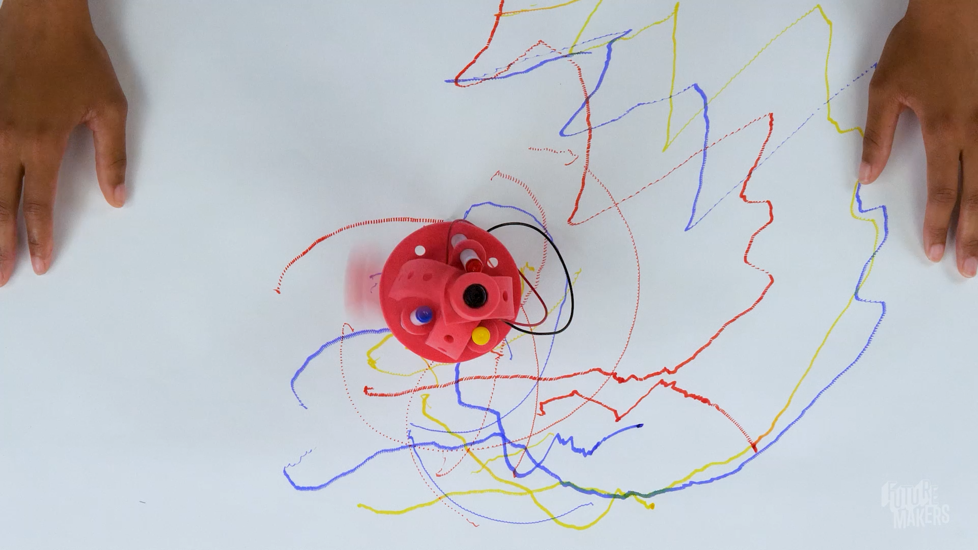
Combine repositionable foam components, a spinning motorized weight, and markers to create a rebuildable machine that draws swirling, spinning doodles! Disassemble, redesign, and combine with a friend. Every build explores vibration, circuits, and the engineering design process.
Get the materials that pair with this educator guide.

Get the materials that pair with this educator guide.
Quick Start gets the main resources in hand. The guide below helps with the decisions that happen before, during, and after students build.
What students build and how the activity works.
Prep questions and pro tips.
Classroom sequence and prompts.
Learning goals and curriculum connections.
Fixes, adaptations, and extensions.
Drawbots are a whole new take on vibrating drawing machines! Learners combine repositionable foam components, a spinning motorized weight, and markers to build a small machine that draws on its own. The modular design means every piece can be rearranged and recombined, so no two Drawbots are alike - and learners can even combine their builds with a friend’s to create more complex machines.
Starting with a core build, learners follow a guided process to create a structure that stands on marker legs, holds a battery and motor, and vibrates when a circuit is completed. From there, they redesign, experiment, and iterate - exploring how changes to weight, balance, and structure affect movement and artistic output. Along the way, they practice the engineering design process, build troubleshooting skills, and discover that there’s always more than one way to make a Drawbot draw.

Question: How can you combine a piece and markers to create a body that stands on three legs?
Question: How can you keep the markers connected so they’re more stable?
Pro Tip: Now is a great time to check in with your learners and make sure everyone’s Drawbot is standing on its own before moving on.
Question: The motor and the battery will need to connect to make a circuit that makes the motor spin - how can we use the rubber band to hold wires to the ends of it?
Pro Tip: Stretch the band multiple times before putting it on the battery. Loosening up the elastic first will make it much easier for learners to get it on without frustration.
Question: Where can we attach the battery to our Drawbot body so it’s held firmly in place?
Question: Where can we insert the motor so it’s held firmly in place, and it can spin?
Question: What parts can we add to the end of the motor to make the motor vibrate?
Question: How can we connect the motor wires to the battery so the motor spins? Note: The colors of wires are not important right now - you can experiment with where which color wire goes later and see what changes!
Question: What will your Drawbot create? Let’s find out!
Question: How could you rebuild it?
Remind learners that it’s okay to fail and try again!
RI.K-2.7 – Use Information from Illustrations: Example: Learners study the build photos to tell the short rectangular-hole foam piece apart from the L-shaped one, matching each picture to the correct motor-mount piece before feeding the motor’s gear through it and wrapping the foam snugly around the motor’s metal body.
SL.K-2.1 – Participate in Collaborative Conversations: Example: Learners talk through where to slide each of their three markers into the circular base with a partner, using words like “even” and “balanced” as they decide together whether a marker needs to move before the Drawbot will stand on its own.
RI.3-5.7 – Use Information from Text Features and Diagrams: Example: Learners follow the numbered build photos to see exactly how the rubber band should wrap the battery and motor wires, noticing from the diagram which wire touches which end before testing whether their own circuit matches the pictured connection.
W.3-5.2 – Write Informative/Explanatory Texts: Example: Learners write a short paragraph documenting one redesign from the Iterate step - for example, moving the unbalanced weight from one gear notch to another - explaining in their own words why that specific change made the Drawbot vibrate in tighter circles instead of long, loose swoops.
RST.6-8.7 – Integrate Quantitative and Technical Information: Example: Learners cross-reference the written troubleshooting list (“motor moves but bot doesn’t move: adjust foam weights, reposition the motor, or change marker angles”) against the build diagrams to decide which single adjustment to try first on a Drawbot that spins in place without traveling.
W.6-8.1 – Write Arguments with Claims, Reasons, and Evidence: Example: Learners write a claim about their Speed Challenge results - for instance, that moving the unbalanced weight farther from the motor’s center made the Drawbot vibrate faster - and back it up with the specific before/after weight positions and drawing patterns they observed as evidence.
K.MD.A.1 – Describe Measurable Attributes of Objects: Example: Learners describe measurable attributes of their three markers - comparing how far each one is pushed through the base and how evenly they are spaced - noticing that a marker pushed in less far, or spaced unevenly from the others, makes the whole base wobble instead of standing flat.
1.G.A.2 – Compose Two-Dimensional and Three-Dimensional Shapes: Example: Learners compose their Drawbot’s body by combining the circular foam base with the three-hole foam connector and the L-shaped motor-mount piece, describing how the round base and the straight and L-shaped rectangular pieces fit together into one three-dimensional structure that stands on its own.
3.MD.B.4 – Generate Measurement Data: Example: Learners measure the spacing between their three marker legs in inches with a ruler, then the class records everyone’s measurement on a shared line plot to compare how far apart legs need to be spaced for a Drawbot to stand without tipping.
4.MD.A.3 – Apply Area and Perimeter Formulas: Example: Learners measure the length and width of the rectangular hole in each motor-mount piece - the short one and the L-shaped one - and use the area formula to confirm both holes are the same size before overlapping them so the motor’s gear can pass cleanly through, then compare the perimeter of the L-shaped piece to the straight piece to see how much more foam edge the L-shape has.
6.RP.A.3 – Use Ratio Reasoning to Solve Problems: Example: Learners time how many seconds it takes their Drawbot to travel the same 12-inch distance with the weight close to the motor’s center versus moved to the gear’s outer notch, comparing the two rates (inches per second) to see how weight placement changes speed.
7.G.A.2 – Draw Geometric Shapes with Given Conditions: Example: Learners treat their three marker legs as the vertices of a triangle and test different spacing conditions - legs spaced evenly apart versus two legs bunched close together - observing which side-length conditions produce a stable stance (a working triangle) and which produce a Drawbot that tips over immediately (no working design).
K-PS2-1 – Plan and Conduct an Investigation of Forces: Example: Learners compare what happens when they place the unbalanced weight close to the motor’s center versus out on the gear’s farthest notch - feeling a gentle wobble from a push near center and a strong shove from a push far off-center - directly comparing how different strengths of push change the Drawbot’s motion across the table.
K-2-ETS1-2 – Develop a Simple Model or Prototype: Example: Learners sketch where they will place the unbalanced weight on the motor gear before attaching it, treating the sketch as a simple physical model, then rebuild it during the Iterate step - moving the weight to a different notch and reshaping the marker legs - to test whether their model needs to change.
3-5-ETS1-1 – Define a simple design problem with criteria for success and constraints: Example: Learners define their own design problem for the Pattern Challenge - build a Drawbot whose marker draws mostly circles instead of straight lines - naming the constraint that they can only use the components already in the kit, no new materials.
3-5-ETS1-3 – Plan and Carry Out Fair Tests: Example: Learners run the Speed Challenge as a fair test, changing only the unbalanced weight’s position on the gear while keeping the same three markers, spacing, and battery in place, to isolate whether weight placement alone - and not some other factor - is what changes the Drawbot’s speed.
MS-PS3-5 – Construct an Explanation of Energy Transfer: Example: Learners trace the energy chain in their Drawbot - chemical energy in the AA battery converts to electrical energy in the wires, then mechanical energy as the motor spins the off-center gear weight, then kinetic energy as the whole structure vibrates - and predict which link in the chain stops first when they disconnect one wire from under the rubber band.
MS-ETS1-2 – Evaluate Competing Design Solutions: Example: Learners run the Collaboration Challenge, combining their Drawbot with a partner’s into one larger machine, then evaluate the combined design against each of their original solo builds using the criteria of speed and how controlled the resulting pattern is - deciding together which original component arrangement to keep and which to abandon.
Check wire connections - each metal end must touch an opposite end of the battery. Make sure the wires are carefully slid under the rubber band on each end.
Adjust foam weights, reposition the motor, or change marker angles. Most importantly - is anything keeping the unbalanced weight on the motor from spinning? Is it stuck on something like a marker?
Adjust leg positioning, length, and angle or shift components for balance. The motor and battery are heavy - where can they be moved to keep things stable?
Check three things: First, make sure the unbalanced weight isn’t bumping into anything like the markers. Second, make sure the weight isn’t pushed too far down past the gear. Finally, ensure the foam weight is correctly attached and the motor is held tightly to the body - motors that are tight to the body make bots that vibrate and move more!