Verify your email
Hi Johny, to view the full content, please verify your email address by clicking the link sent to youremail@gmail.com
Resend Verification Email
Invent a wind-up flying machine that transforms stored energy into flight! Learners design and attach a custom fuselage, wind the rubber band to store elastic potential energy, and master the Lift-Off launch technique to send their creation soaring. Along the way, they explore aerodynamics, symmetry, and the engineering design process through iterative wing modifications.
Get the materials that pair with this educator guide.

Get the materials that pair with this educator guide.
Quick Start gets the main resources in hand. The guide below helps with the decisions that happen before, during, and after students build.
What students build and how the activity works.
Prep questions and pro tips.
Classroom sequence and prompts.
Learning goals and curriculum connections.
Fixes, adaptations, and extensions.
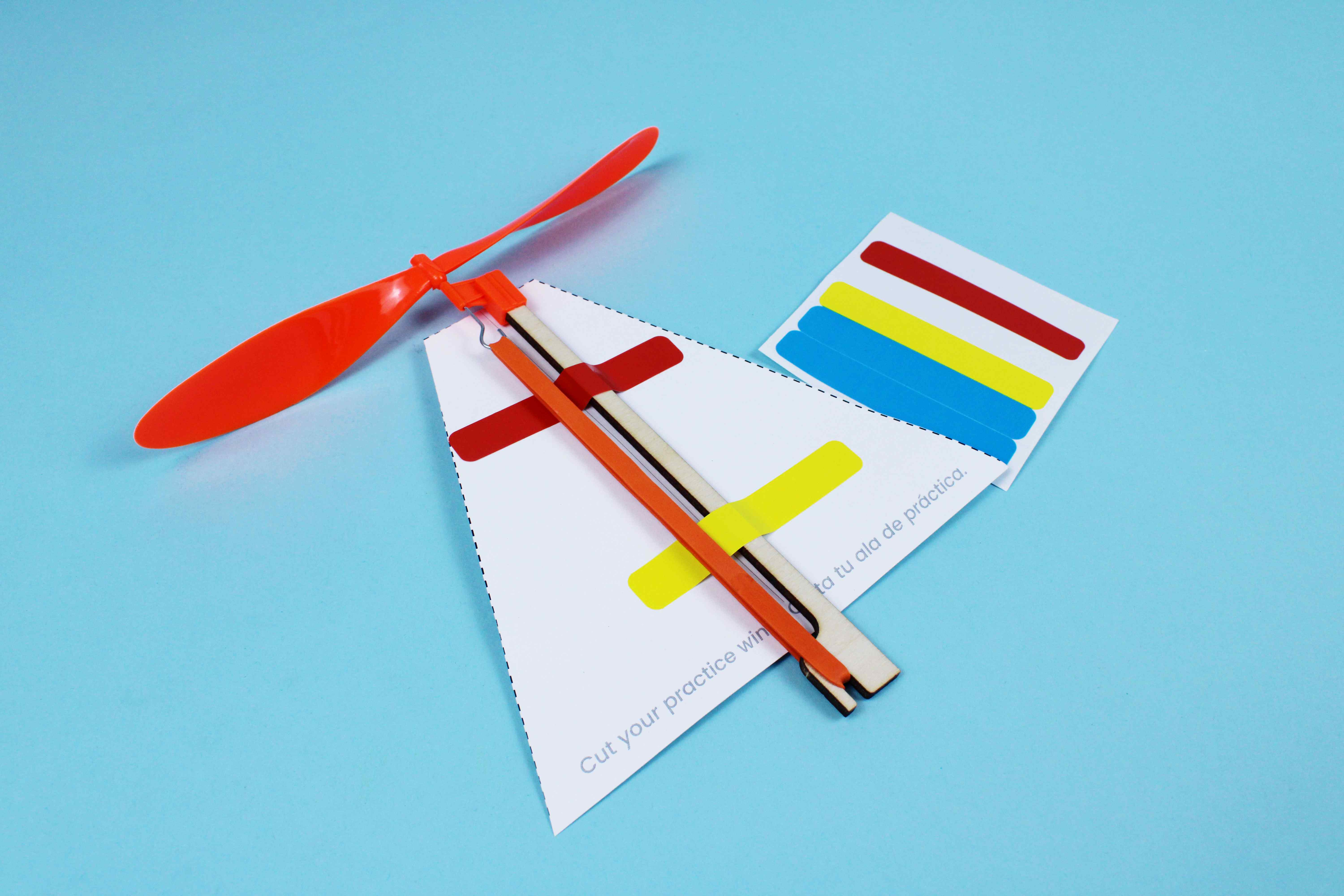
Flying Machines challenge learners in grades K and up to build a rubber band-powered flying machine from a propeller, fuselage stick, and custom-designed wings. As they wind the propeller and practice the two-step Lift-Off release technique, learners experience the transfer of elastic potential energy to kinetic energy firsthand. The activity takes as little as 10 minutes at an activity station or extends to 60 minutes with wing iteration challenges.
What makes Flying Machines unique is the emphasis on iterative design and resilience. After a basic flight test without wings, learners draw, cut, and attach symmetrical fuselage designs, then test how each modification affects flight distance, direction, and duration. The engineering design process comes alive as learners adjust wing shapes, sizes, and rubber band tension, building persistence and critical thinking through repeated launches and refinements.
Scissors for cutting out fuselage and wing designs from the card stock template.
Additional scrap or construction paper for learners who want to create alternate wing designs beyond the included template.
Projector and screen for displaying the Flying Machines presentation slides that guide learners through the build.
Drawing materials additional markers or colored pencils for fuselage decoration (optional but encouraged).
Question: How could you combine these parts to assemble a unique Flying Machine?
Question: What do you notice about the hooks on the propeller and the fuselage stick? Why do you think they are shaped that way?
Question: What do you think is happening to the rubber band as you wind the propeller? Where is the energy going?
Question: Will the Flying Machine fly without any wings attached? What do you predict will happen?
Question: How do you think adding wings will change the way the Flying Machine flies?
Question: Where on the fuselage stick should you place the wing? Why does placement matter?
Question: How did adding the wing change the flight compared to your test without wings?
Question: What wing shape do you think will make your Flying Machine fly the farthest? The highest? Can you make it turn?
Question: What would you change to make your Flying Machine fly farther, fly longer, or turn left or right?
RI.K-2.7 – Use illustrations and words in a text to describe key ideas: Example: Learners review the instructional diagrams on their cardstock sheet and identify how each labeled part - propeller, fuselage stick, rubber band - contributes to flight, describing the function of each component in their own words.
SL.K-2.1 – Participate in collaborative conversations: Example: Learners discuss their wing design choices with peers after each test flight, describing what happened when they changed wing shape or size and listening to classmates' observations about their own Flying Machines.
RI.3-5.7 – Interpret information from diagrams and text: Example: Learners analyze the energy transfer diagram showing elastic potential energy converting to kinetic energy, then explain in their own words why winding the rubber band clockwise stores energy that the propeller releases as motion.
W.3-5.2 – Write informative/explanatory texts: Example: Learners document their wing evolution process on the worksheet, explaining why each successive wing design performed differently and how changes in symmetry, shape, or size affected flight distance.
RST.6-8.7 – Analyze diagrams and scientific texts: Example: Learners create annotated diagrams of the energy transfer process in their Flying Machine, labeling where elastic potential energy is stored in the wound rubber band and where kinetic energy is released through the spinning propeller.
W.6-8.1 – Write arguments to support claims with evidence: Example: Learners write a brief analysis arguing which wing design achieved optimal flight, citing measured distances, number of rubber band twists, and wing dimensions from their wing evolution worksheet as evidence.
K-2.MD.A – Describe and compare measurable attributes: Example: Learners measure the length and width of their cardstock wings using rulers, comparing dimensions across iterations to understand how larger or smaller wings affect flight distance and stability.
K-2.G.A – Identify and describe shapes: Example: Learners identify geometric shapes in their wing designs - triangles, rectangles, and curves - and describe how the symmetry of their fuselage shape helps the Flying Machine fly straighter.
3-5.MD.B – Measure and estimate lengths and represent data: Example: Learners measure wing dimensions across four iterations on the wing evolution worksheet, recording length and width data to identify which measurements produced the longest flights.
3-5.G.A – Reason with shapes and their attributes: Example: Learners apply geometric reasoning to optimize wing aerodynamics, exploring how triangular, rectangular, and organic wing shapes create different flight paths and determining which symmetrical designs achieve the most stable flight.
6-8.RP.A – Understand ratio concepts and use ratio reasoning: Example: Learners experiment with the ratio of rubber band twists to flight distance, testing increments of 25, 50, 75, and 100 twists and analyzing how the relationship between stored energy and flight performance is not strictly linear.
6-8.G.A – Solve real-world problems involving geometry: Example: Learners use geometric principles to calculate wing area and assess its effect on lift, comparing flight results from symmetrical versus asymmetrical wing designs and applying proportional reasoning to optimize fuselage balance.
K-PS3-1: Energy and Motion: Example: Learners explore how winding the rubber band clockwise stores elastic potential energy that converts to kinetic energy when the propeller is released, observing how more twists produce faster spinning and longer flights.
K-2-ETS1-2: Engineering Design: Example: Learners follow the design process by building, testing, and improving their Flying Machine, starting with a bare fuselage flight, then adding a test wing, and finally designing a custom wing shape to improve performance.
3-PS2-1: Forces and Interactions: Example: Learners investigate how wing shape and size affect the forces acting on their Flying Machine, testing whether bending wing tips changes the flight path from straight to curved, and observing how symmetry affects stability.
3-5-ETS1-3: Planning and Carrying Out Investigations: Example: Learners systematically test different wing designs using the wing evolution worksheet, changing one variable at a time - shape, size, or symmetry - documenting flight results across four iterations to identify the most effective design.
MS-PS3-5: Conservation of Energy and Energy Transfer: Example: Learners analyze the complete energy transfer chain in their Flying Machine - from mechanical work winding the rubber band, to elastic potential energy stored in the twisted band, to kinetic energy released through the spinning propeller - and explain why energy is conserved but changes form at each stage.
MS-ETS1-2: Developing Possible Solutions: Example: Learners apply an iterative design process to optimize flight by systematically varying wing geometry, rubber band tension, and launch technique, evaluating each solution against criteria of distance, height, and stability before selecting their best design.
The most common cause is not enough stored energy. Have learners wind the propeller clockwise at least 50–70 times - they should see big bumps forming in the rubber band. You can always add more twists. If it still won't fly, check that the rubber band is not pinched or stuck against the fuselage.
The propeller is being wound in the wrong direction. It must be turned clockwise (to the right) to fly upward. Review clockwise vs. counterclockwise with learners - younger students often need a quick refresher before winding.
Learners are likely releasing the fuselage and propeller at the same time. Coach them on the lift-off technique: release the propeller first, let it spin to build momentum and generate lift, then release the fuselage. Timing is everything.
Check that the rubber band can move without obstruction. Tape, stickers, or decorations near the propeller area can block rotation. The rubber band should never be stuck down - it needs to move freely to transfer energy.
Use masking tape or painter's tape to attach wings - it holds well and removes cleanly for iteration. Remind learners that symmetry is helpful for balanced flight, but encourage them to experiment with different shapes and sizes as part of the design process.