Verify your email
Hi Johny, to view the full content, please verify your email address by clicking the link sent to youremail@gmail.com
Resend Verification Email
Animate a scene with a hand-powered mechanism! Learners engineer an automata - a historic folk-engineering invention that uses rotational motion, cams, and followers to make a sculpture move and tell a story. Every Scene Machine starts with a laser-cut cardboard frame, special foam wheels and cams, and paper straws, and grows into a one-of-a-kind animated scene when learners add their own art, characters, and story. It's engineering, visual art, and language arts in one spinning sculpture.
Get the materials that pair with this educator guide.
Get the materials that pair with this educator guide.
Quick Start gets the main resources in hand. The guide below helps with the decisions that happen before, during, and after students build.
What students build and how the activity works.
Prep questions and pro tips.
Classroom sequence and prompts.
Learning goals and curriculum connections.
Fixes, adaptations, and extensions.
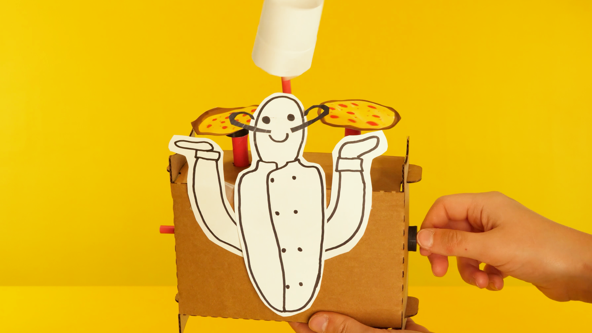
Scene Machines introduce learners to automata - hand-powered mechanisms that turn rotational motion into animated scenes. Inspired by the automata collections at the Exploratorium and the Cabaret Mechanical Theater at the American Visionary Art Museum in Baltimore, this Spark combines mechanical engineering, storytelling, and visual art into a single build.
Each learner receives a laser-cut cardboard sheet (which folds into an automata frame), four standard paper straws, one jumbo paper straw, a set of special foam followers and cams, and a visual instruction sheet. Using those parts and a guide tube cut from the jumbo straw, learners build a working round-and-round mechanism with a cam, a cam follower, and an aligned axle system.
The build follows nine steps: explore the kit, fold the automata frame, cut and install a guide tube, insert the axles and cam, test how the round-and-round mechanism rotates, brainstorm a story, prototype a scene with paper and tape, finalize by disguising the frame with art, then iterate with new mechanisms or added parts. Advanced learners can unlock intermediate (up-and-down via offset cams) and advanced (side-to-side via linkages) mechanisms to bring more complex scenes to life.
Scissors for cutting the jumbo straw to pinky-length for the guide tube and for cutting paper, cardboard, and linkage straws.
Tape for attaching prototype pieces, reinforcing slipping cams, and holding scene elements in place.
Drawing materials (pencils, markers, crayons) for sketching brainstorms and adding color to final scene components.
Paper and thin cardboard for prototyping and building the final scene components that disguise the frame.
Question: What do you notice about the different pieces in your kit? Which ones do you think will move, and which ones will hold everything in place?
Question: Which parts of this cardboard sheet are meant to come off, and which parts need to stay connected for the frame to hold together?
Question: Why do you think one straw is wider than the others? What job might a "guide tube" do inside the mechanism?
Question: If a cam is the piece that drives the motion, and a follower is the piece that rolls along the cam, where in your frame do you think each one should go?
Question: When you turn the cam axle, which way does the follower spin? What happens if you slide the cam to the other side?
Question: What is the one-sentence story you want your Scene Machine to tell? What needs to move to bring that story to life?
Question: Before you commit to the final scene, how can you quickly test whether your mechanism will actually move the part of the story you want to animate?
Question: How will you turn your cardboard frame into a place - a landscape, a stage, a room - so your scene feels complete?
Question: Now that your Scene Machine is telling a story, what could you add, change, or unlock to take the scene further?
RI.K-2.7 – Use illustrations and words in a text to describe key ideas: Example: Learners use the visual instruction sheet and the Planning Sheet to identify the parts of their Scene Machine - the cam, the follower, the guide tube, the axle - matching the labeled illustrations to the real foam and cardboard pieces as they fold and build the automata frame.
SL.K-2.1 – Participate in collaborative conversations: Example: Learners describe their Scene Machine's story to a partner in one sentence, using automata vocabulary like "cam," "follower," and "axle" to explain how the mechanism animates the element their story is about - rehearsing the narrative that made them pick a round-and-round motion in the first place.
RI.3-5.3 – Explain relationships between a series of concepts in a text: Example: Learners explain the cause-and-effect relationship between turning the cam axle and the follower's rotation, tracing how the cam on one axle makes contact with the follower on the other - then predicting what happens when the cam is slid to the opposite side of the follower.
W.3-5.3 – Write narratives to develop real or imagined experiences: Example: Learners use the Scene Machine Planning Sheet to title their automata and write the one-sentence story it tells, then develop that story into a brief narrative that describes what moves, why it moves, and how the scene changes when the cam turns during the final gallery-walk presentation.
RST.6-8.3 – Follow a multistep procedure when carrying out experiments: Example: Learners follow the nine-step Scene Machines build sequence in order - frame fold, guide tube, axles, cam, rotation test, brainstorm, prototype, finalize, iterate - recognizing that skipping the prototype stage is the single most common reason a final scene's mechanism fails when art supplies are already glued on.
SL.6-8.1 – Engage in collaborative discussions with diverse partners: Example: Learners compare round-and-round, up-and-down, and side-to-side mechanisms during the unlock phase, arguing which mechanism would best animate a particular story element and citing evidence from their prototype test runs to support the engineering decision.
2.MD.A.1 – Measure the length of an object by selecting and using appropriate tools: Example: Learners use their own pinky finger as a measuring tool to determine the length of the jumbo straw that becomes the guide tube - a real-world moment where an informal unit of length is exactly the right tool for the job, and where measurement directly controls whether the mechanism works.
K.G.A.1 – Describe objects using shape names and relative positions: Example: Learners describe the foam parts using shape vocabulary - the large disc and medium disc (circles), the small stoppers, the rectangular cardboard frame - and use positional language to explain "the follower sits on top of the cam" and "the stoppers go on the outside of the frame" during assembly.
4.MD.C.5 – Recognize angles and understand concepts of angle measurement: Example: Learners observe how the cam rotates through a full 360-degree turn and how the follower rotates in response - tracking the angle of rotation of each axle and noticing how the arrow they drew on the cardboard test disc sweeps through a complete circle every time the cam axle makes one revolution.
4.OA.C.5 – Generate and analyze patterns: Example: Learners predict the repeating pattern of the round-and-round mechanism - when the cam axle turns forward, the follower axle turns in a predictable direction, and every subsequent revolution produces the same result - recognizing this consistent cyclical pattern as the defining feature of a rotational mechanism.
7.G.B.4 – Know the formulas for the area and circumference of a circle: Example: Learners measure the circumference of the large and medium discs and reason about how circumference relates to the mechanical output of their automata - a larger cam disc sweeps a longer path per rotation, producing a wider up-and-down movement when used with the offset hole in the advanced mechanism.
7.RP.A.2 – Recognize and represent proportional relationships between quantities: Example: Learners investigate the proportional relationship between cam-axle rotations and follower-axle rotations - one full turn of the cam axle produces one full turn of the follower axle in a standard round-and-round - and discuss how changing cam size would change this proportion in a redesigned mechanism.
K-PS2-1 – Motion and Stability: Forces and Interactions: Example: Learners apply a push and a turn to the cam axle and observe how the follower rotates in response - feeling firsthand that a force applied at one point in a mechanical system causes motion somewhere else, and noticing that the size of their turn determines how far the follower moves.
K-2-ETS1-2 – Engineering Design: Develop a simple sketch, drawing, or physical model: Example: Learners sketch a one-sentence scene on the Brainstorm Sheet before they build, drawing where the moving element will go on the frame and labeling which mechanism will drive it - then building a low-fi paper-and-tape prototype of that sketch to test whether the mechanism animates the story the way they imagined.
3-PS2-1 – Forces and Interactions: Cause and Effect: Example: Learners investigate how the direction and position of the cam cause the follower to rotate one way or the other - sliding the cam from the left of the follower to the right of the follower, then turning the cam axle, and observing that the follower's direction of rotation reverses. A direct, observable cause-and-effect relationship in a mechanical system.
3-5-ETS1-3 – Plan and carry out fair tests to identify failure points: Example: Learners systematically troubleshoot a stuck round-and-round mechanism by isolating one variable at a time: first checking whether the cam and follower are in contact, then whether the stoppers need to slide, then whether the follower axle is sticking out too far and blocking the cam - a textbook failure-point test they can repeat on the up-and-down and side-to-side unlocks.
MS-PS3-2 – Develop a model to describe energy transfer: Example: Learners model how mechanical energy transfers from the cam axle to the follower axle through contact force - the turning hand applies force to the cam, the cam's rotation pushes the follower at the point of contact, and the follower translates that force into its own rotation, animating whatever scene element is attached. A concrete energy-transfer chain they can watch in real time.
MS-ETS1-3 – Analyze data from tests to identify similarities and differences among several design solutions: Example: Learners compare the three mechanism unlocks - round-and-round, up-and-down via offset cam, and side-to-side via linkage - evaluating which mechanism best animates each scene element, documenting trade-offs between mechanical simplicity (round-and-round) and expressive motion (side-to-side linkage), and justifying their choice using observations from their prototype test runs.
Check three things in order: (1) Is the cam actually touching the follower? Slide the stoppers to re-align the cam so the follower sits on top of it. (2) Is the follower axle sticking out too far and blocking the cam's path? Adjust the end of the axle so it doesn't contact the cam. (3) Is the guide tube seated all the way into the frame hole? If it's loose, the axle wobbles and loses contact with the cam.
Foam holes can stretch. Reinforce by adding stoppers on either side of the cam so it can't slide along the axle, or wrap a small section of tape around the straw axle to thicken it and grip the cam hole again.
Bend the tabs gently before pushing them into the slots - don't force them or the cardboard will tear. If the tabs keep popping out, double-check the short sides are fully folded along the perforations before trying to lock them.
The saved cardboard corner pieces become the feet. If you already tossed them, a piece of tape folded like a triangle can work as a temporary stand, or lay the frame on its side and coach the scene to be read from the side.
The guide tube is probably in the way. Remove the guide tube for the advanced builds so the straw can move freely. Also try using a larger cam - the bigger the cam, the bigger the up-and-down motion.